Saturday, October 26, 2013

balance

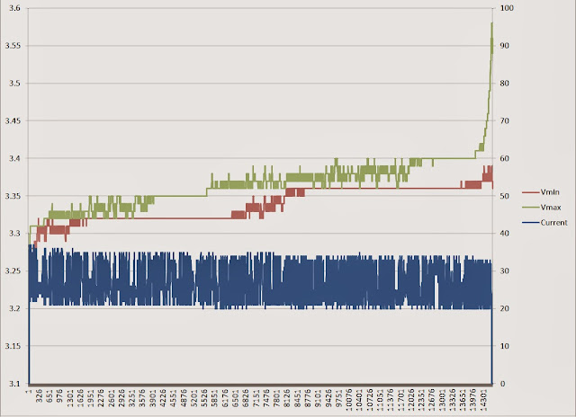
Step 34:  Watch cells balancing at night.  The battery side charging fuse is an Edison base type, 30A (it is rated for 125 volts alternating current but I've verified performance with direct current to be used plus I like its thrift - fuse holder is a ceramic flood lamp socket).  If needed I can do balancing sessions by swapping the fuse for a light bulb of chosen wattage to match the cell balancing load electronics.  A 200W light bulb limits the charge current to a little over half an amp.  My cell balancing loads are around a fifth of an amp, a 75W bulb.  A little imbalance may take a while to bleed off. 

Kits are available to increase balancing capability but I would avoid expense by manually bleeding the highest cell in the pack, and seeing how that went.

Every second the BMS communicates with the circuit board on each cell causing it to blink.  When a cell is being bled down to equalize the pack it leaves its light on.  I don't think I'll have to put up Christmas lights this year.


dc/dc

Step 33:  Install DC/DC converter to keep 12V system charged.  Up until now my 12V system has just been running off a 12V car battery.  This works but lights are dimmer and I would worry when having to run wipers and lights for extended periods.  The Mean Well S-350-12 DC/DC is wired to be on all the time.  It sits next to the motor controller in the trunk.


ac repair

Step 32:  Repair air conditioning.  A high side hose crimp blew while picking the kids up from school making a violent sound.  I had the hose repaired $20 and was pleased to see that the system was serviceable from underneath. Haste during the repair broke the condenser that came with the car.  So it was replaced with an aftermarket unit $84.  The system was open during some rain so the dryer $15 was also replaced before charging $32 back up.

broke


access

What you want is ~24psi on the
low side and 160psi on the high
side.  I left the high side
slightly lower, at 150psi.


new condensor


Thursday, October 10, 2013

revisit 24

Step 31:  Revisit step 24.  After tightening one of the charger output fuses the output jumped up 20A.  I can now fully charge in 5 hours.  The charger may be put in the trunk someday but for now I charge at home.  The charge stations in town cost 6x the rate I can get at home.

I replaced the charger outlet behind the drivers front wheel. 


26.7A


This charge is for a 31.7 mile drive, mixed driving, 60mph, some traffic, not hypermiling.  That's 333Wh/mile, or 100 miles per (cost of a) gallon (at $3/gal).

Wednesday, October 9, 2013

power brakes

Step 30:  Install power brake vacuum pump.  Without any vacuum one could sufficiently stop, but holding the car on a hill would get old quickly.  A purpose built electric vacuum pump and reservoir from an electric vehicle supply house is added to help out.


A bracket to hold the reservoir is fabricated, you may recognize it bolted to the top of the motor in step 5.


It fits in front of the battery.  The reservoir takes a few seconds to pump up after every application of the brake pedal.  It works really well!  Power brakes really improve the driving experience.

Saturday, September 28, 2013

monitor

Step 29:  Monitor battery.  Add instrumentation to monitor battery.

I wired a plug-in clock to the BMS controlled charging relay (DPDT).  I set the clock at noon and start the charge.  The duration of the battery charge is recorded when the clock stops.  My charge is constant current so I can then calculate amp hours consumed since the last charge.  

The 12V output in the old charger is broken, I've replaced it with another 12V charger.


old school


I can communicate with the BMS using a terminal app on my iPhone.  The terminal app is what logged the run around the block in step 28.  If the BMS has a fault this is how I read it.


new school


The old school is producing a number around 315Wh/mile.  The new school 290Wh/mile.  I have more trust in the old school at this point.  While driving the new school appears to blank out under high current getting stuck for periods at 0A or 497A.  I need to rewire the current sensor using shielded cable.


new school current sensor

Friday, September 27, 2013

range

Step 28:  Figure efficiency.  


I can go 45 to 55 miles on a charge.  


I found the bad connection that was not allowing my BMS current sensor to work.  With the new current sensor operating I logged a run around the block.


Monday, September 23, 2013

get legal

Step 27:  Get legal.  I got an inspection on my lunch break.  So there you go, it takes 27 steps to convert a BMW 2002 to electric drive.  

I believe step 8 can be skipped.  A 9" motor is so huge for this little car I do not think it will need a fan.  Driving around it's apparent that the motor controller is the weak point heat-wise, and it has a fan and heat sink (step 25).


I also would skip step 13.  The ammeters chosen were of poor quality and do not work correctly.  I do not think you need to be looking at a gauge anyway.  As a driver you can tell when you're sacking the battery and when you're not.  


I drove it to work and lunch then to an Irish session in the evening, 42 miles total!  It then took (very roughly, to be refined) 137Ah to reach full charge.  Saving 20% capacity for long life this means my range driving like an excited kid is about 45 miles.  Half of that was flying down highways.  I suspect keeping under 45mph would greatly increase the range. 

Friday, September 20, 2013

test drive

Step 26:  Go for a test drive.  The new controller is faster and quieter.  With the muggy rain I was able to test the AC's ability to defog the windshield.  With two vents pointed up the fog quickly evaporated.


Monday, September 16, 2013

better, faster, ...

Step 25:  Work out the kinks.  Smoke escaped from the old PMC controller.  5 of its 8 power transistors are blown.  I suspect some had blown early in test driving.  It still operates the remaining 3 switches, but alone they can't provide enough current to push the car.  I will try to repair it but in the interest of getting on the road it will be replaced with a Curtis 1231c.  This has a higher current limit of 500A and a silent switching frequency.  


The Curtis 1231c is widely used and requires a heatsink.  I found one online and bolted it to the bottom using thermal grease.  I borrowed the fan from the old PMC and mounted it on the back.  There is good airflow out the end.


Saturday, August 31, 2013

charge

Step 24: Charge batteries. The cells came around half full and I've driven some laps in the neighborhood. This charger, along with my motor controller, are from a 1981 Jet Electra. The charger is dual output, charging the 12V battery while powering the BMS. The BMS turns the charger off when the battery is full using a relay.  This charger could be put in the trunk and used at charging stations around town with the help of an adapter.  But the charge voltage profile combined with the number of cells I chose only allows for a trickle charge, a C/20 rate. Saving 20% capacity for long life a full charge will take 14 and a half hours. I don't expect to use a full charge everyday. 

I put the charger outlet behind the drivers front wheel, with a fuse at the battery. The location was partially chosen based on body damage in the vicinity.  Creepage and clearance was gained in the 7-pin connector by leaving an empty pin next to the high voltage pins.


After what seemed like forever she reached full charge. The BMS terminated the charge.

Thursday, August 29, 2013

test drive

Step 23:  Go for a test drive.  Everything seems to work.  The next step is working out the charging system.


first ride goes to helper

Saturday, August 24, 2013

wire batteries up

Step 22:  Wire batteries up.  These being expensive batteries I want to make sure they are protected from damage.  A battery management system (BMS) is employed.  A gracious EV-cohort donated an Elithion BMS needing only minimal additional components.  This BMS monitors voltage and temperature and disables the drive if a cell is in danger of being damaged.  It does the same during charge.  This BMS uses a small circuit board that attaches to each cell, these are daisy chained together and relay data to the BMS controller.  I've installed the BMS controller tucked up under the dash.  I will be able to view the status of the battery pack with my iPhone and a rs232 dongle.

front bank

rear bank, tucked into the back of the
trunk for good weight distribution


BMS controller, rat nests allowed

Wednesday, June 26, 2013

install batteries

Step 21:  Install batteries.  I picked up the cells and they look great.  They all have a listed capacity around 200Ah and an initial resistance reading around a quarter of a milliohm.  

The first task is to secure them in the car.  I'm simply using vinyl strapping to secure them to the plywood platforms already bolted in the car.  The 3rd picture is of the cells that will go in the trunk.

Tools acquired:  strapping tensioner and crimper


Wednesday, June 19, 2013

track batteries

Step 20:  Track batteries.  To save shipping costs I will pick the batteries up from the UPS freight terminal once they arrive.


Thursday, June 13, 2013

order batteries

Step 19:  Order batteries.  This gets its own step.  A lot of the money in this car will be in its batteries.  I chose to order directly from CALB (China Aviation Lithium Battery) because they have a presence in California and my friend had met the salesman there a few years ago.  They had them in stock stateside and are packaging them up right now!  I'm getting 30 of the CA180FI cells.  It's going to be a very nice battery.


Wednesday, May 1, 2013

power cables

Step 18:  Make power cables.  I'm using 2/0 gauge.  The cables are orange, for easy identification.  To save money I painted black cable.  I'm going with the crimp-only crowd in the debate over the best way to make lug connections, copper to copper.  Adhesive lined shrink tubing is put over the cable-lug connection to keep it clean.  Anti oxidant grease is used when bolting lugs down.

Tools acquired: hammer crimper

There will be 8 cables:

  • battery plus to main contactor
  • main contactor to motor plus
  • main contactor to motor controller plus (under car, in rear)
  • mid-battery connection (under car)
  • motor controller output to motor minus (under car)
  • motor armature to motor field (pictured below)
  • battery minus to emergency disconnect switch
  • emergency disconnect switch to motor controller minus


Saturday, April 13, 2013

battery mounts

Step 17:  Make platforms to mount batteries.  I'm going simple with 3/4" plywood.  In the front the plywood is secured to the motor mount and a horizontal brace, in the rear bolted through the floor of the trunk.  The only protection the batteries will have will be provided by the car and hood or trunk lid.  My idea is to use polyester strapping to strap the batteries to the plywood.  It will be about 200 pounds of batteries for each location.


There will be 14 batteries in the front and 16 in the rear.


Saturday, February 16, 2013

air conditioning

Step 16:  Achieve refrigeration.  This part needed to be worked out before putting a large battery in the way.  Route the A/C hoses tucked away, a large battery is going to go in here.  The A/C ports will be accessible with the battery in place, and the compressor serviceable from underneath.  The high side port, pictured (red), is tucked under the dryer.  The low side port is up against the firewall.  


The jumper cables are for running the compressor on 12V while filling and testing.  The traction motor draws roughly 600W idling at 12V.  The air conditioning system increases power draw by roughly 700W.  

The battery may look like this box.  So I want to work the kinks out of the air conditioning before being encumbered with it.


Evacuated and filled with R134a.  Ice-cold!


Well, it was ice-cold then the compressor made noises and seized up. I learned that a refrigerant compressor has to be mounted right-side-up.  There is an oil plug on the body which has to be within 90 degrees of up.  It probably ran for 30 minutes upside down - don't do that!  


New compressor installed.  Air conditioning complete.

Tools acquired: AC gauges and cheapy vacuum pump from Harbor Freight

Friday, January 18, 2013

trunk seal

Step 15:  Replace trunk seal.  Much of the electronics will be located in the trunk.  Replace the seal to keep them dry (hopefully).


The layout of components is depicted below.  In place of the 12 batteries pictured though I'll have 30 (3.2V each).


The big silver box in the top picture is an old PMC transistor controller from my first EV:  the rebuilt Jet Electra - which it pushed around for 4 1/2 years.  The switching frequency is only 4kHz so it's audible and makes AM radio interference that sounds like a Harley Davidson.  I inspected the insides and it still looks very clean though I may replace the electrolytic caps as cheap insurance in case they're dried out.